What forces must be pondered when designing metal pallet racks? How do we verify that the structure will be suitable to withstand all loads? These and other issues are those which should be taken into account in the design of this type of rack, with the goal of ensuring its stability and resistance, and therefore the overall security of the installations.
The European EN 15512 norm, according to its definition, specifies the requirements for structural design applicable to conventional pallet racking (selective racks) manufactured from steel components, designed to store palletised unit loads and subject to essentially stationary loads.
 It has become the main benchmark on this matter, and provides additional technical information required for the implementation of the Eurocodes. In addition, designers must also provide for the EN 15620, EN 15629 and EN 15635 standards as guides for the specifications of the storage system, the required tolerances during assembly and the safe operation of the installation.
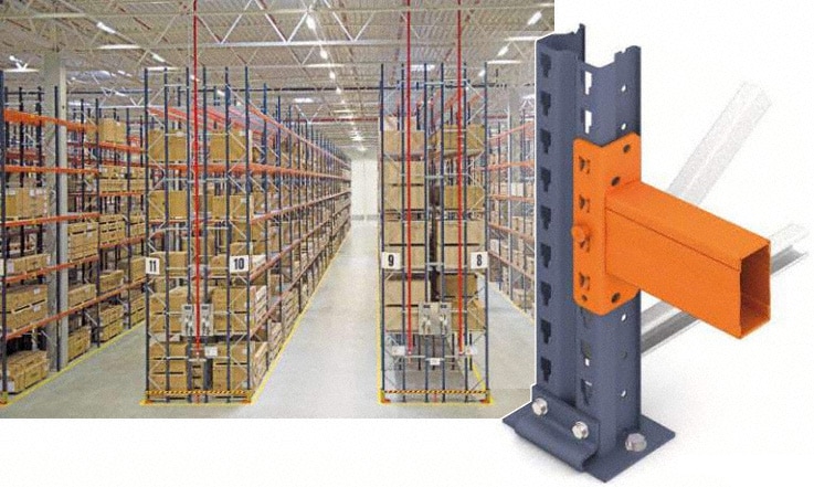
Likewise, conventional racks for palletised loads are metal structures, generally formed by components made out of thin, cold-formed, steel sheet metal. They are able to withstand heavy loads, while the installation is designed to be as lightweight as possible; consequently the rack’s own weight rarely exceeds 5% of the load stored in the facility’s interior.
On the other hand, it is imperative that this type of installations for palletised loads be versatile, to be able to adapt to different load types. For this reason, the connections between the main parts of the structure must be adjustable, and quick and easy to assemble.
The uprights of these structures usually have perforations along the entire profile, while the beams include connectors provided with hooks that fit into the perforations of these uprights.
Basic structural components
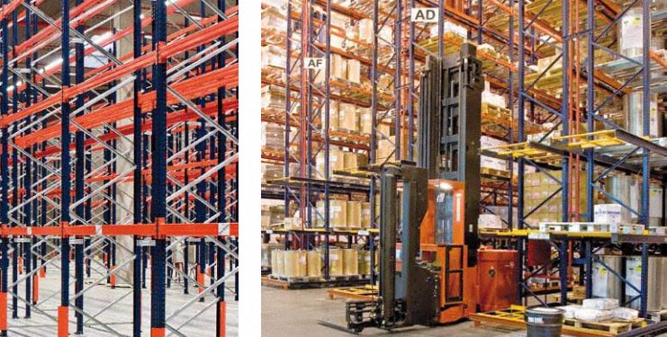
- Frames: are vertical pieces composed of two uprights joined together by beams and cross-ties forming a lattice.
- Uprights: these tend to be cold-profiled components of thin sheet metal, with open sections and are always perforated, which makes them prone to distortion and torsional type sagging.
- Beams: are horizontal pieces that bear the burden of the pallets. These tend to be cold-profiled and have connectors on their ends for attaching them to frame uprights.
- Connectors: are parts welded on to the ends of beams to attach them to the uprights. They are equipped with hooks that fit into the perforations of the uprights.
Calculation types: general and individual
The calculation is carried out in two stages:
- General analysis of the structure: Normally filiform, two-dimensional (2D) models with second order calculations applying the finite element method are used. In some types of installations, calculations are also frequently done via 3D models in accordance with the EN 1993-1-1. This analysis must incorporate the modelling of the actual behaviour of the connection between the upright-beams and the frame-ground.
- Individual verification of pieces: Once the overall analysis is performed, it is vital to check the correctness of the design by verifying the buckling and the tensions of the pieces that make up the racking. Basically, the following items are verified:
-
- General stability of the installation.
- Stress state of frames: uprights and diagonals.
- Base plates: pressure on the slab and anchorage.
- Beams: buckling and stress state.
- Connectors.
General analysis: structural model
For general analysis, it is usual to consider two, two-dimensional (2D) structures in concurrent vertical and perpendicular layouts with respect to the storage aisles. In the model calculation, the following requirements are observed:
General analysis
- Filiform model.
- System lines through the CG (centre of gravity) of the gross section, or also through the CG of the actual cross section.
- Terms of section corresponding to the gross section of the pieces (or also of the actual cross section). In this analysis the aim is to obtain:
- The internal forces on the different pieces for their subsequent verification, combining the down-aisle and cross aisle calculations.
- Checking the overall stability of the installation.
It includes two types of analysis:
- Down-aisle analysis: analysis in 2D on a vertical layout parallel to the load aisles. This analysis also includes the semi-rigid connections of the upright-beam and upright-floor, obtained by testing.
- Cross-aisle analysis: analysis in 2D on a vertical layout perpendicular to the load aisles. Usually involves the articulated upright-floor joint. In both cases, the global imperfection can be modelled as:
- The tilt of the agreed uprights to the imperfection.
- Horizontal forces at the height of the load levels corresponding to the imperfection.
Type of analysis according to the classification of the structure
This classification is based on the relationship of the expected load design in regards to the critical load of the structure. According to the coefficient obtained by this relationship, the need to perform a second order calculation will be determined.
Individual analysis: verifying elements
In the verification of the different elements that make up the structure the following concepts, among others, must be taken into account:
Uprights - Frames - Anchorage plates
- Upright mainly function by compression and flexion.
- The use of the reduction factor for buckling, obtained by laboratory testing or by using theoretical formulas.
- The internal forces obtained from the down-aisle and cross-aisle calculations will be jointly perpended.
- Axil force on the diagonals of the frame.
- Axil force and momentum on uprights’ footplates.
- Axil and shear force on fastening anchorage to the slab.
Beams – Connectors
- Working primarily with bending and shearing forces.
- Buckling (deflection) is limited to a maximum of L/200. Occasionally, for certain installations smaller value deflections are required.
- Consideration of the cross-aisle forces of location.
- Verifying the shear force and deflection in the endplate.
Blocks of bracing - Vertical and horizontal bracing – Spacers
- The brace diagonals work exclusively on axil force.
- Verification of the deflection and shear forces on the elements that connect the diagonals of the vertical bracing to the frames (bracing spacers).
- The actions of the bracing increases the forces on the uprights and beams that form part of the block of bracing or that are adjacent to it.
- The eccentricity of the actions of the vertical bracing in respect to the racks requires a study of the torsion behaviour of the elements that form part of the block of bracing, as well as the racks.

Actions
There are different types of actions that may affect the strength and stability of the racks, so that it is also imperative to contemplate them when setting up an installation of this kind. The actions on the racking are classified into several groups:
Permanent actions
- Weight of the racks.
- Permanent loads and various equipment supported by the racking.
Variable actions
- Weight of the pallets.
- Weight and actions due to mobile loads on platforms and walkways.
- Actions due to the location of the pallets (vertical + horizontal).
- Actions on the positioning profiles.
- Actions due to storage equipment guides.
- Actions due to the imperfection in the elements and assembly.
- Other actions arising from national regulations (wind, snow, etc.).
- The weight of the pallets together with the general imperfection deemed as a single action, which in turn is the most relevant (unfavourable).
Accidental actions
- Forklift blows.
- Actions on security profiles.
- Seismic actions.
Load states and the combination of actions
It is viewed as appropriate and sufficient to study the two load states listed below, considering the following actions or load cases:
- Permanent actions + the most unfavourable variable action.
- Permanent actions + 0.9 x (the totality of variable actions).
- Permanent actions + variables + incidentals.
State Service Limit (SSL)
In each of the load cases the buckling of the structure’s parts subject to the corresponding unweighted actions (nominal loads) is studied:
- Verifying the overall stability of the structure.
- Verifying beam deflection
Ultimate Limit State (ULS)
In each of the load cases the tensional state of components subjected to the corresponding weighted actions (affected by factors of security) is studied. In the verification formulas of the elements the combination of forces (down-aisle + cross aisle) must be considered. It is also necessary to ponder the uncertainty as to the different actions that can affect the racking (described previously).
To do this, there are established security coefficients considered, for both the load coefficient and the material, and which can range between 1.0 and 1.5. Some countries have specific national legislation which obliges you to use greater weighting coefficients in the facilities that are built on its territory (A deviations).
Eccentricities

When the design and/or handling of the storage system allows the pallets to systematically become off-centred, the increased load that causes this off-centring on beams and braces must also be taken into account in the design of the structure.
Likewise, the eccentricities of the lines of the structural system must be observed, in the event that they are deemed excessive.
Eccentricities in the positioning of the pallets
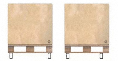
- Asymmetric position of the pallets in regard to the beams.
- Load is not evenly distributed on the pallet.
- Load overflow in regards to the pallet.
Eccentricities of the diagonals of the vertical bracing
Although the diagonals of the vertical bracing are not physically connected to the racks on the junctions that form the neutral lines of the uprights and the beams, in the 2D calculations the diagonals can be viewed as attached to these junctions, provided that the eccentricities of the same are kept below certain values depending on the width of the brace and the edge of the beams.
The same happens with the diagonals of the frames.
Conclusion: the safety of the installation and responsibilities
Lastly, we want to point out that in a large part of the incidents that occur in palletised installations, human error interferes and are primarily caused by scraping or impacts of forklifts against the racking.
On the other hand, these impacts may represent higher than normal actions on the racks, than those established in the EN15512 norm. Thus, not only is it imperative for the manufacturer to carry out a good structural analysis and design of the installation, but it is also makes good use of the same, so that actions against the racking does not exceed those considered in the installation’s structural calculation.
This is all the fruit of many years of experience, and studies and trials by FEM (Federation of European Maintenance) and other agencies. It is essential to keep in mind:
En 15620. - Steel static storage systems. Tolerances, deformations and clearances.
- Flatness of the slab and its buckling underload.
- Clearance between pallets, and between the pallet and racks.
- Clearance between racks and civil works.
- Aisle width according to the load unit, the forklift type and the number of pallet locations per hour.
En 15629. - Steel static storage systems. Specification of storage equipment.
Individual responsibilities of the different system suppliers that make up the storage equipment.
En 15635. - Steel static storage systems. Application and maintenance of storage equipment.
- Designation of a person responsible for the security of the storage equipment.
- Safe load sign
- Education and training of the warehouse staff.
- Damage to the racks and assessment of the level of damage.
- Regular inspections.
Software for the structural calculation of racks
Currently, all the mentioned analysis throughout this article are done via computerised calculation programmes. Mecalux has applied their extensive experience in design, manufacture and installation of warehouse systems to the development of a powerful design software, capable of finding the best option for each warehouse layout, the dimensions of the storage structures and the most ideal profiles. In this way, optimization of capacity and cost of the warehouse is procured, with the utmost safety.
